
Service · Engine Out Procedures
We design the escape route and the take-off weight together, against terrain modelled at 1 arc-second, and find the heaviest take-off that still clears with full margins. We propose alternative obstacle splays and turn heights, and deliver the procedure that fits your operating policy.
The trade-off
Weight sets V2, V2 sets the turn radius — and the speed sets how much bank you may use: 15° at V2, 25° at V2 + 15.
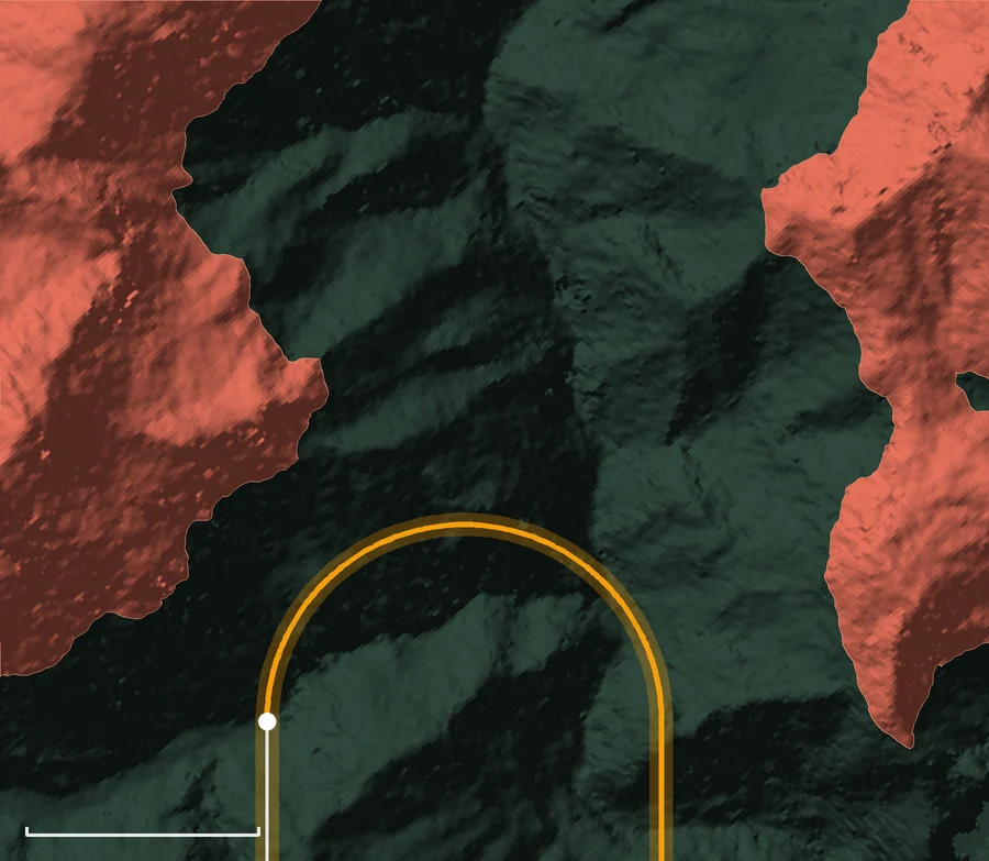 V2 125 kt · 15° bank
Lower V2 → smaller radius, but at V2 the bank is limited to 15° → less payload.
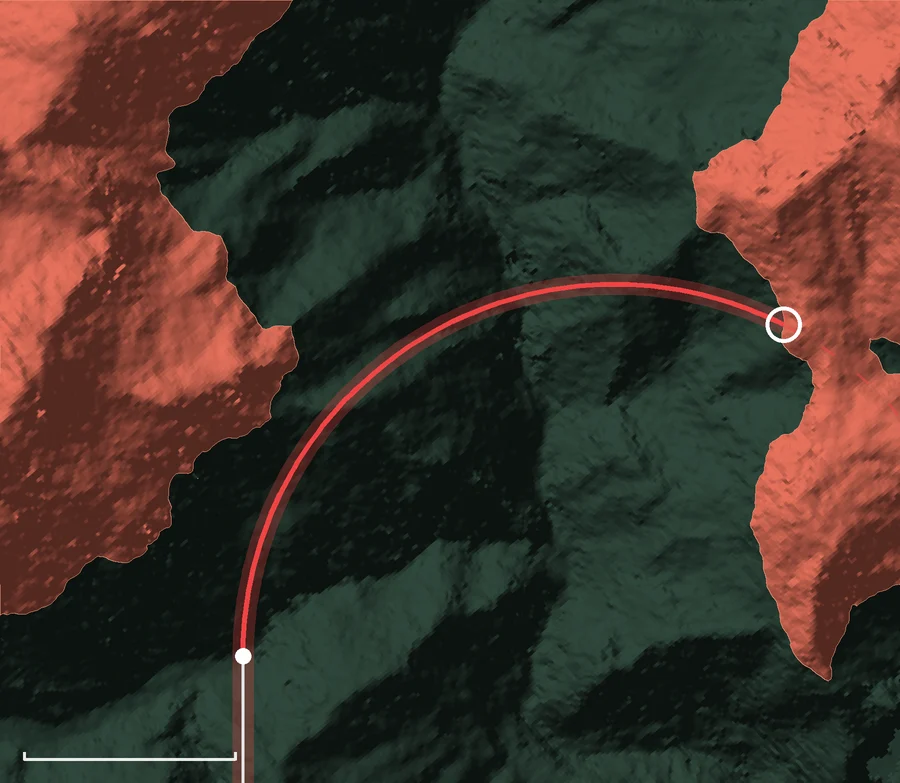 V2 180 kt · 15° bank
Higher V2 → larger radius → impacts the terrain.
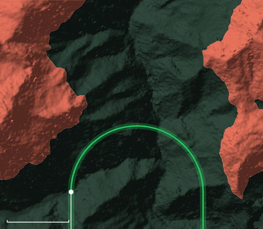 V2 + 15 = 185 kt · 25° bank
Fly V2 + 15 → 25° of bank → optimum turn radius → maximum payload.
terrain above the net flight path · ±300 ft corridor · inbound track · scale bar 1 NM
Real valley and net altitude from the case study below · illustrative speeds and banks · true airspeed, still air · r = V² / (g · tan φ)
The optimisation
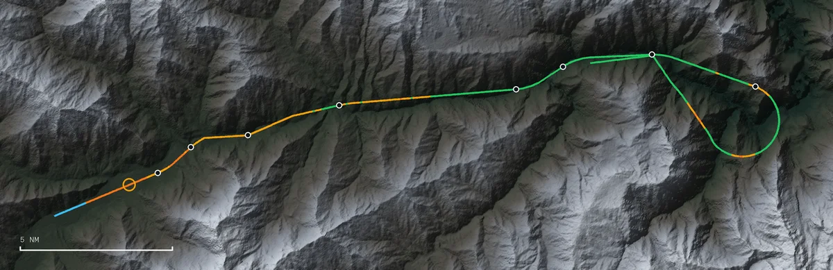
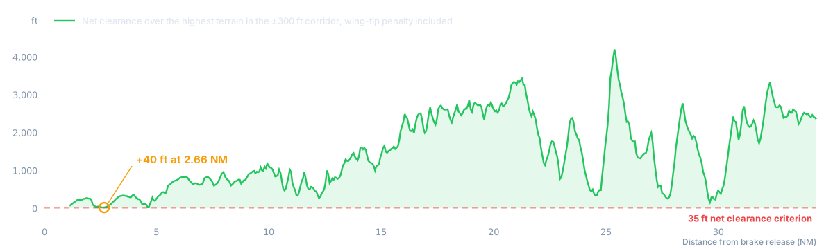
The answer is the heaviest weight that keeps 35 ft of net clearance — and the procedure that flies it.
Case study
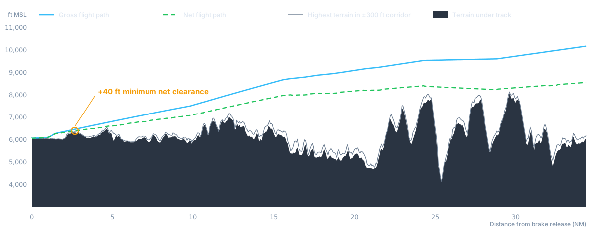
An escape route through a confined valley with a turn-back, submitted to the civil aviation authority.
How we do it
Boeing BPS and BCOP on the certified SCAP data — or the AFM, digitised chart by chart.
Gross path less 0.8 %, per 14 CFR 25.115 and 121.189.
1 arc-second elevation model, ±300 ft corridor, wing-tip penalty in turns over 15° of bank.
Minimum margin and where it occurs, with every input traced to its source.
What you receive
Initial conditions, vertical and horizontal profile, and the flight path point by point: weight, speed, rate of climb, bank, heading, height, gradient and time.
The procedure in Google Earth: the flight path at its real altitude over the terrain, with every turn point.
Methodology, regulatory basis, traceability of every number to its source, assumptions and operating limitations.
Airport, runway, aircraft type and dispatch weights. We will tell you whether your numbers hold.